Drone Flight Controller
IN PROGRESS
9/20/20244 min read
Overview
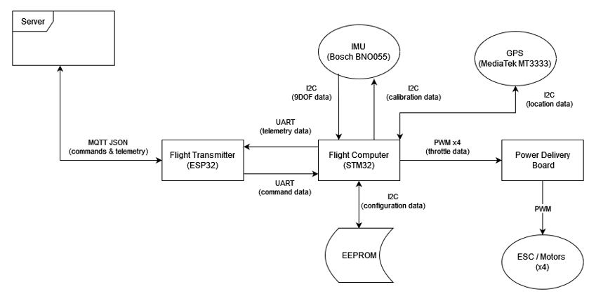
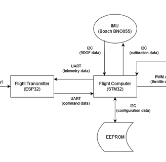
This project involved designing and building a fully custom flight controller for a quad-copter. I used an STM32 to interface with sensors and to perform the control calculations. The ESP32 was used for a WiFi connection and to process commands.
Objectives:
Create a highly reliable system that requires minimal user input to function.
Implement all drivers myself, meaning no external libraries for sensors.
Use MQTT to send commands to the drone and receive telemetry back.
Send telemetry data to Unity to render the drones position in real time.
Have the drone hover at 1 meter and hold position.
Why I Decided To Build It:
I was inspired after watching a video about the F-22 Raptor's fly-by-wire system (see my write-up on the home page). I wanted to explore similar control principles on a scale I could tackle myself. Since quad-copter technology is much more affordable than a $350 million dollar jet fighter, I figured it would be a platform with enough complexity to implement similar control theory (PID controllers, data fusion, state approximation, ect). Additionally, I wanted to have a summer project that pushed my embedded programming knowledge and allowed me to design to a multifaceted system.
Implementation
Major Components
Sensors
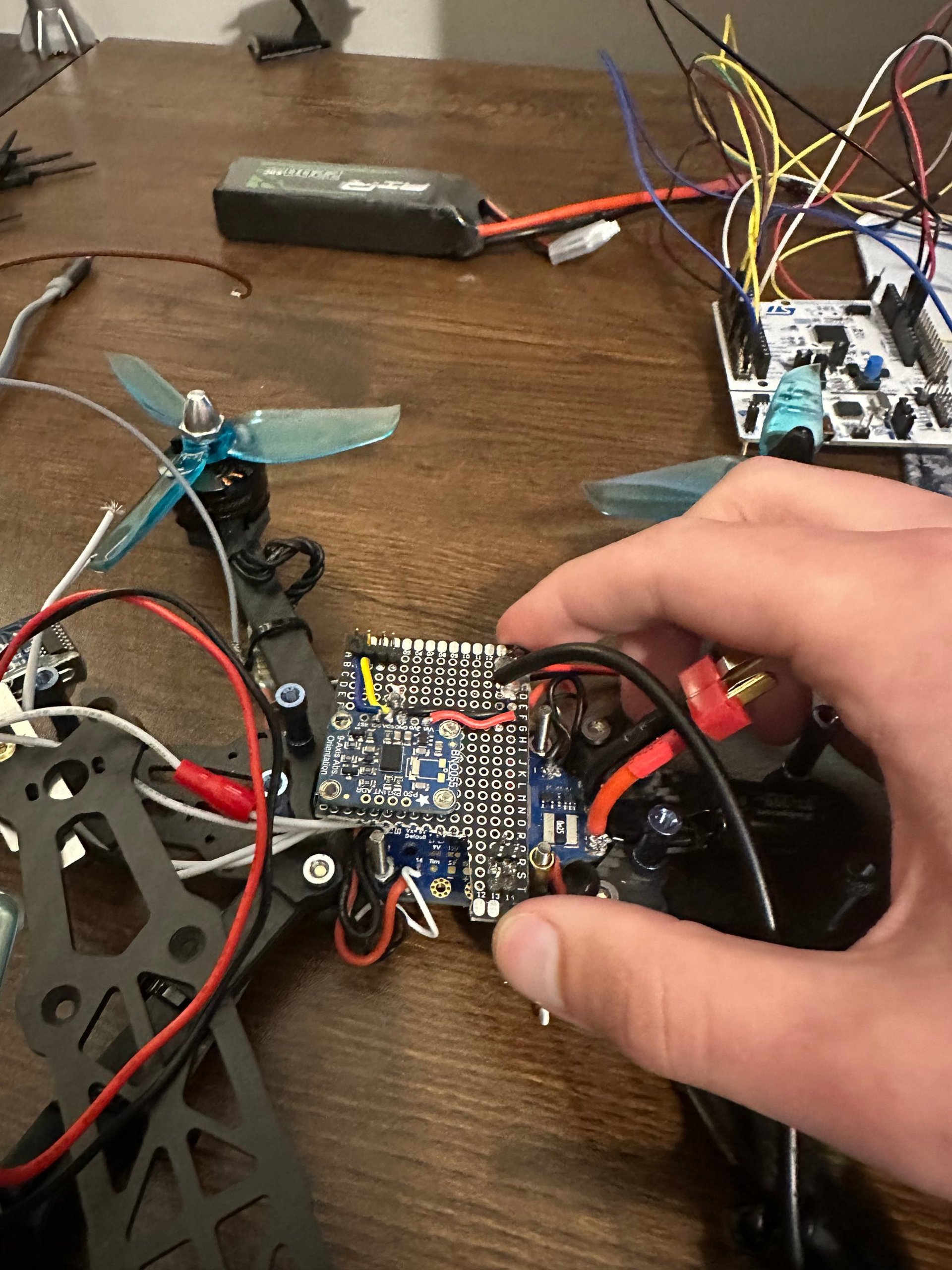
Bosch BNO055 IMU
MediaTek MT3333 GPS
HC-SR04 Ultrasonic Sensor
24LC32 EEPROM
SoloGood 20A ESC (x4)
Hardware
STM32 L476RG
ESP32 WROOM32
Matex PDB
Feichao 2300KV Brushless Motor (x4)
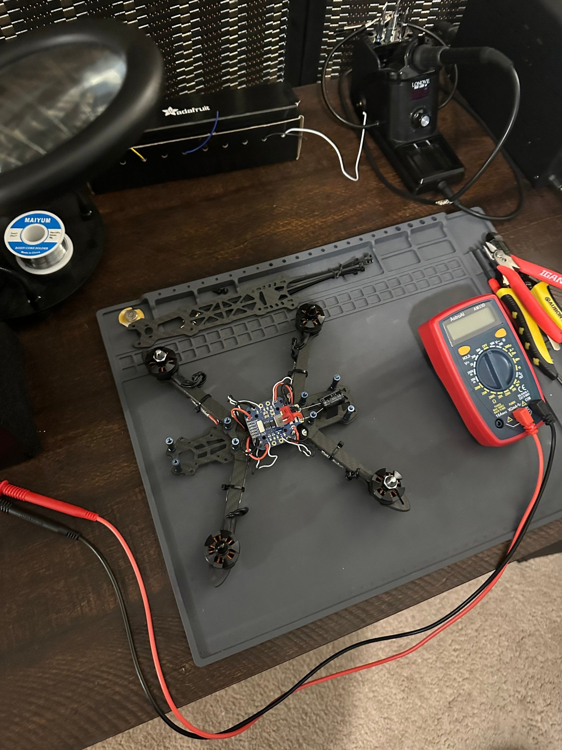
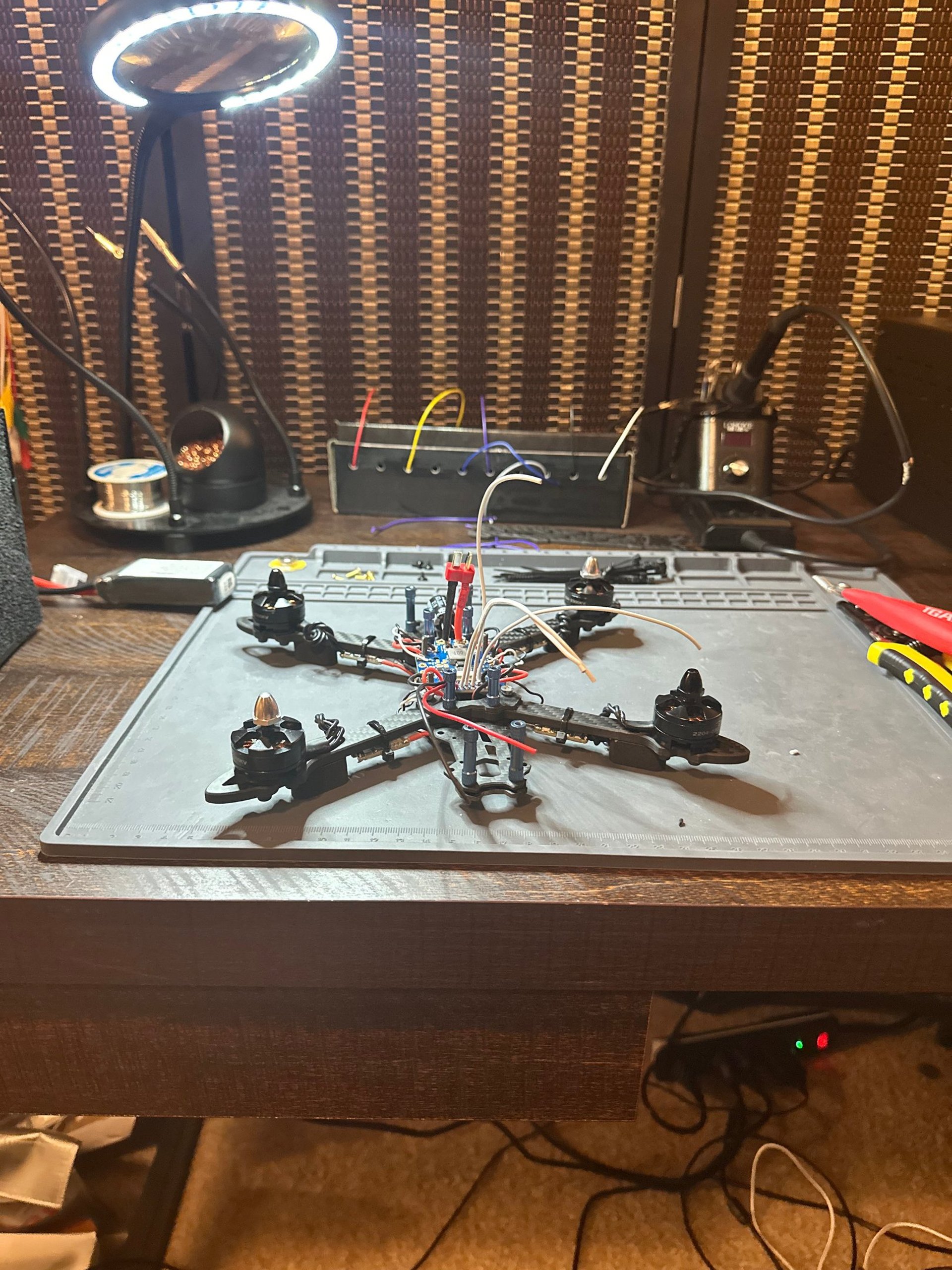
225mm FPV Drone Frame
This project was broken into 2 major milestones:
Sensor Integration: Integrating the sensors with the STM32, and have it send telemetry data to the ESP32. Additionally, implement the communication from the ESP32 to my home server over MQTT.
Flight Control: Design a flight control algorithm that would allow me to use GPS, IMU and ultrasonic data to control the height of the drone, essentially an auto-hover mechanic.
Sensor Integration
I really wanted to write my own drivers and not use outside libraries. This was done so I could get a deeper understanding of embedded devices, and to tailor the interfaces based on my requirements. I used C++, so each sensor has its own class.
Sensors: Each sensor class inherits from SensorBase, which provides a common interface for initialization, sending telemetry data, and shutting down. This allows each sensor to be managed uniformly, while still using the appropriate communication protocol (I2C or UART) through a dereferenced pointer. This design enables flexibility, as new sensors can be easily integrated by inheriting from the base class and specifying their communication protocol and unique identifier for verification.
Flight Computer: I chose UART for intercommunication between the flight computer and transmitter because of its reliability in noisy environments. Protocols like SPI or I2C relay on clock signals, and can be disrupted by high inductive noise generated by the drones motors, leading to data loss. However, compared to clock based protocols UART has a much lower data transfer rate and overall transfer speed. This means that it will take more clock cycles to send the same data packet over UART verses I2C or SPI. To mitigate this, I implemented DMA (Direct Memory Access), allowing the STM32 to offload data transfer tasks to a dedicated memory controller. This ensures the flight computer remains updated with command data. The flight transmitter will toggle a pin to high, indicating to the flight computer that a command is ready to be read.
Flight Transmitter: The flight transmitter is built using an Arduino and serves as the bridge between the flight computer and the server using MQTT. It serializes telemetry into JSON, which is then transmitted to the server. It de-serializes commands into a byte stream, and sends it to the flight computer. A key feature of command system is its robust error handling: when a command is sent, the transmitter waits for an acknowledgment. If a response is not received or a checksum mismatch is detected, the transmitter sends an error state and reports the issue back to the server, providing reliable command state estimation and fault tolerance.
Challenges & Lessons Learned
Out of all my personal projects, this one presented the most "unexpected" challenges and lessons. These ranged from software, packaging, physical ect. Heres a list of some of my favorites:
Challenge: Carbon Fiber Conductivity
While running a motor test, I learned that carbon fiber is conductive by shorting the filtering capacitor to the frame of the drone. This short caused a lot of smoke, and if it wasn't for my power delivery board's diode I would've fried all my ESC's.
Solution: I insulated all of the conductive surfaces, and made sure each component was isolated from ground.
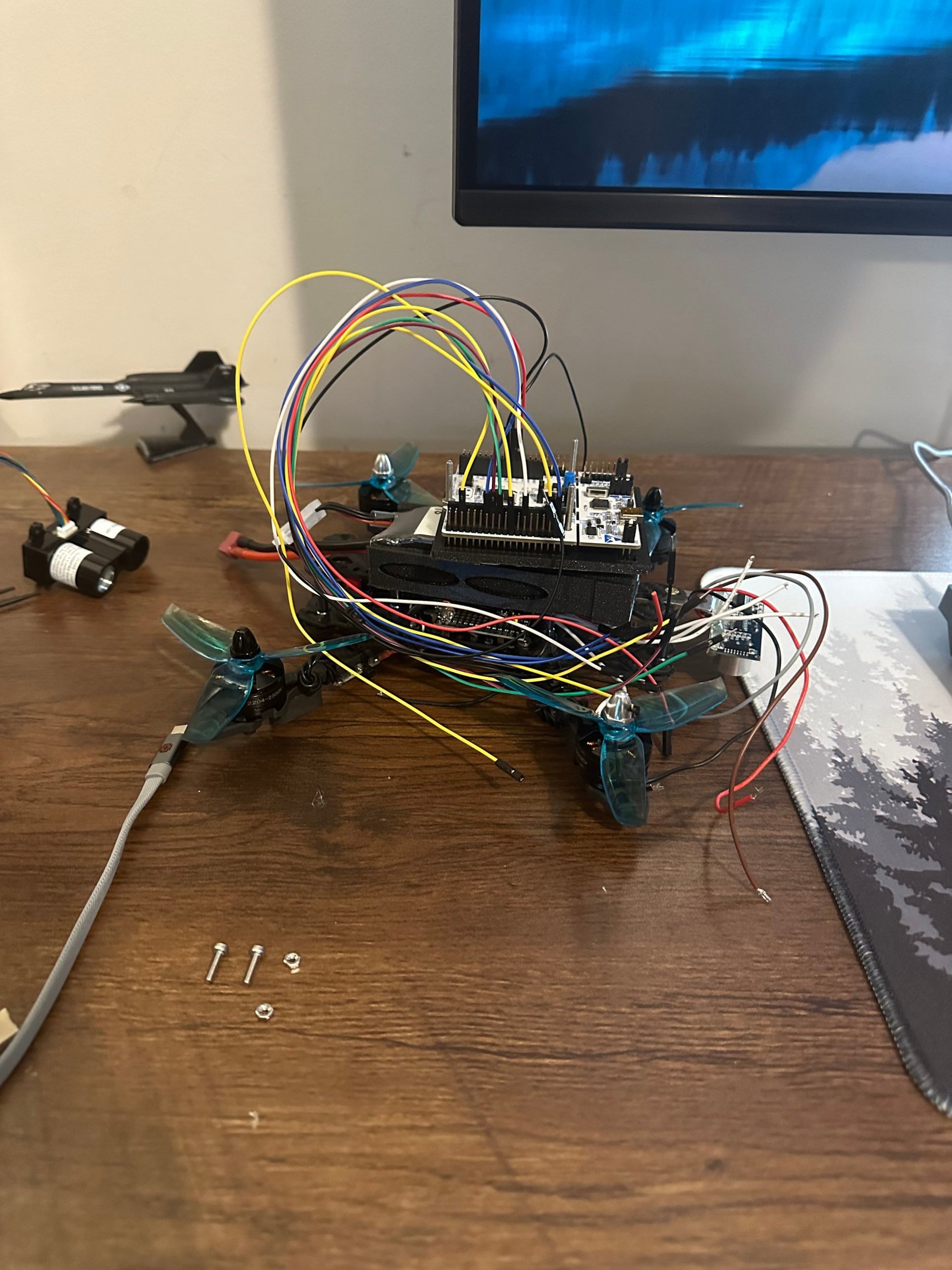
Challenge: Packaging and Space Constraints
During this project, packaging was a major issue. I had selected a pretty small chassis to mount everything to. While this was cheap, I had very little mounting points for all my breakout and discovery boards.
Solution: I stacked everything as best I could, using custom cases that I 3D printed. However, unless I purchase a different chassis, this problem is going to persist.
Challenge: Vibrations
The high frequency vibrations are causing 2 major issues: every screw is backing out of their taps, and the IMU data is almost unusable because of how inconsistent the data is.
Solution: Using rubber and foam on each motor, I dampened the vibrations from the source. Additionally, I re-positioned the IMU and surrounded is with adhesive and rubber to isolate it from the frame. I also used loctite to ensure the screws wouldn't back out.